


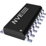
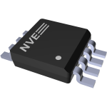
The NVE AAT001-10E angle sensors use unique tunnelling magnetoresistance (TMR) elements for large signals and low power consumption. The sensor provides sine and cosine signals defining the angle of rotation, the outputs are proportional to the supply voltage of 5.5V (max) and peak-to-peak output voltages of 0.2V/V over a full rotation which are much larger than conventional sensor technologies. The AAT001-10E sensors from NVE consist of two half-bridges with a typical bridge resistance of 1.25MΩ for ultra low power applications in an ultraminiature TDFN6 package.
The AAT001-10E sensor contains four sensing resistors at 90° intervals and are connected as two half-bridges providing the sine and cosine voltage outputs. For each half bridge the resistance of one element increases and the other decreases as the field rotates, thus the bridge resistance, device resistance and output impedances remain constant with rotation.
Typical applications for the ATT001 series include:
The below table gives the full specifications of the NVE AAT angle sensor series including the AAT001-10E:

2. “Fixed Bias” means a fixed airgap between the bias magnet and sensor so the magnetic field at the sensor is constant.
3. “Variable Bias” means the magnetic field strength at the sensor can vary across the specification range.
4. Maximum deviation of either output from an ideal sine wave.



 Deutsch