Isabellenhüttes Busbar Shunts – Your solution for current sensing battery management systems & high-current application
The automotive industry is currently undergoing a transformation. Electromobility is gaining in importance in all vehicle sectors – from passenger and commercial vehicles to passenger transportation. The focus here is primarily on the complete electrification of vehicles and less on the hybrid technology that has been widespread to date. Accordingly, pure electric motors and their components must become increasingly powerful, precise, reliable and durable.
Both hybrid and electric vehicles are typically high-current applications in which an accurate battery management system (BMS) is of great importance. Three central parameters must be recorded as accurately as possible in the BMS in order to provide accurate information about the range of an e-vehicle: the cell voltage, the cell temperature and the current flow. Isabellenhütte’s busbar shunts and analog sensors are suitable for measuring high currents. This white paper covers the features, characteristics and possible applications of the different busbar shunt variants. It explains what distinguishes the components of the Isabellenhütte component as well as their specific use cases.
Current measurement across a measuring resistor works by measuring the voltage drop directly across the resistor:
Source Voltage (U) = Resistance (R) x Current (I) + Thermoelectric Voltage (Uth) + Induced Voltage (Uind) + Voltage drop across leads (Uiext).
The analog measurement signal is amplified, then converted into a digital signal and provided to the evaluation electronics. In this case, fault voltages not caused by a current flow (e.g., due to influences of the material or the design) can falsify the measurement result – especially in the case of low-ohmic shunts where the voltage drop is very small. Also to be considered is the power dissipation, which cannot be neglected at very high currents.
Isabellenhütte’s resistance materials are physically optimized in such a way that disruptive influences are kept to a minimum from the outset. The matching design and optimized PCB layout also improve the measurement performance of the resistor. Due to the low-ohmic values of the shunts, the power loss and thus the heating in the component can also be kept low. In addition, the components maintain the specified tolerances in the complete temperature range, at full load and over the entire life cycle.
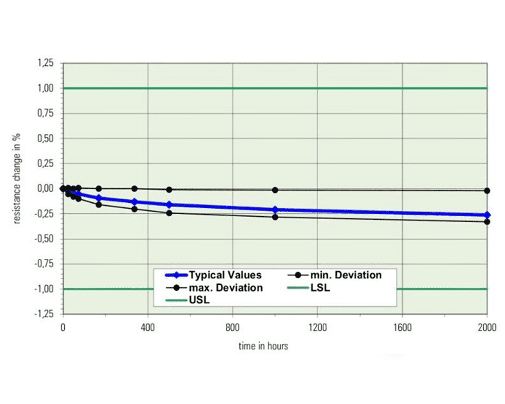
Long-term stability is an important parameter with regard to the quality of a current sensor, which is evaluated as a function of the operating temperature. Isabellenhütte’s busbar shunts are characterized by very good long-term stability. The temperature-related drifts are only slight, even in continuous use. To achieve this, the resistance materials must be stable against corrosion and not undergo any metallurgically induced changes of state. During production, the resistance alloys undergo a temperature stabilization process that optimizes the long-term properties of the components. Stability values in the ppm range per year are possible with these alloys.
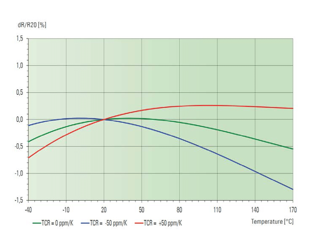
When considering the temperature dependence of resistors, the temperature coefficient TCR plays an important role. This coefficient indicates how much the resistance value changes over a given temperature range and is measured in ppm/degree of heating (in Kelvin). The smaller this change due to heating, the better it is for the application.
There are other factors that can affect the temperature coefficient, such as the contacting capabilities. If the connection is not made properly, the temperature coefficient of the resistor may be distorted due to the influence of the measuring line or contacting.
The Isabellenhütte busbar shunts already have a very good TCR value. Optimized positio¬ning of the contacting options, as recommended by Isabellenhütte, can further improve the TCR value. This reduces the measurement error in the overall system; the user receives the best possible measurement result.
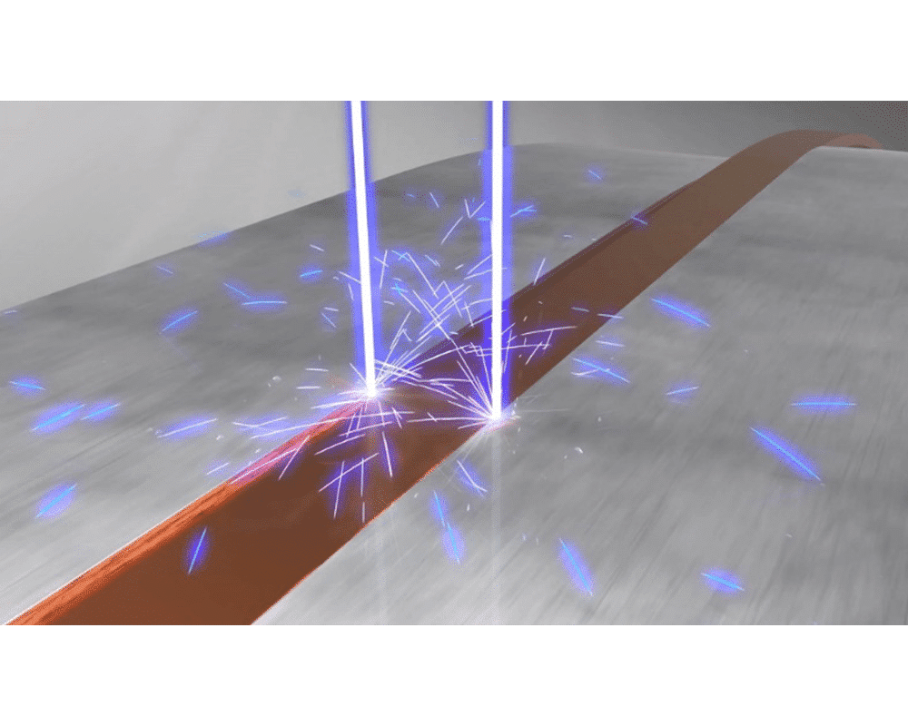
The busbar shunt manufacturing process has an extremely positive influence on the load capacity of the busbar shunts. Due to their special structure, the heat generated in the resistor material is efficiently dissipated through the welded copper terminal, which has high thermal conductivity and heat capacity. Due to their high electrical conductivity, the solid copper terminals in turn ensure uniform current density and heat distribution in the resistor. This results in a low internal heat resistance.
Due to these properties, the resistors can withstand a high load at full power up to very high terminal temperatures – the derating point of the so-called power derating curve is therefore high. This manufacturing process avoids hotspots and achieves a high pulse and continuous load capacity.
The standard busbar shunts are components for high current applications that do not have a contacting option of the kind integrated in the analog sensors. In this case, the voltage taps must be connected by the customer. The busbar shunts are used in 12 V, 24 V and 48 V applications as well as in high voltage applications at > 400 V. They form the basis fora current measurement in the Battery Junction Box (BJB), alternatively also called the Battery Disconnection Unit (BDU), and are produced using electron beam welding technology.
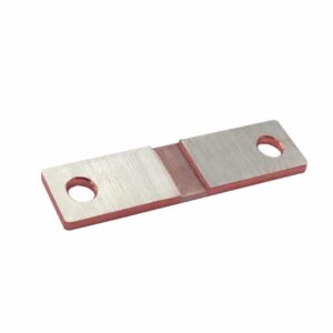
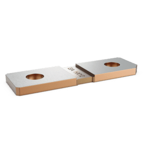
They consist of two copper strips that are electron-beam-welded together with a resistance alloy (with a high copper content) to form a composite material. Thanks to this technology, they offer a high degree of flexibility, as the composite material can be adapted to a wide range of shapes and applications in terms of stamping and bending. Isabellenhütte’s various resistor series comply with the RoHS directives and are qualified in accordance with the high requirements of the AEC-Q200 standard for the automotive sector.
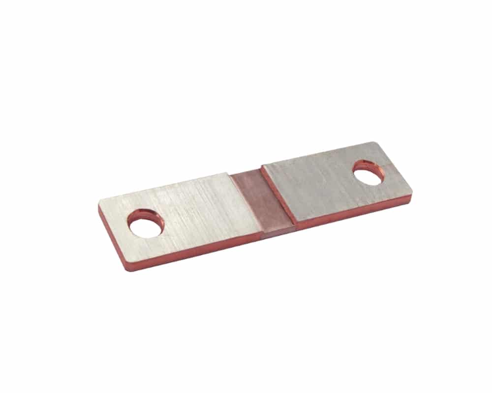
The BAS is the basic version of the busbar shunts for current measurement of battery currents. Possible applications include all types of hybrid and electric vehicles such as cars, trucks, forklifts or industrial trucks. Other potential applications include current measure-ment in welding equipment or in stationary or mobile energy storage systems. The trend with regard to the use of busbar shunts is clearly moving towards ever lower resistance values. The higher currents that must now be measured in the e-mobility sector are also accompanied by higher power dissipation, so developers want to keep this to a minimum by using resistors with the lowest possible resistance values.
The BAS is available with resistance values of 35, 50, 100, 200 and 500 μOhm. Depending on customer requirements, there are now around 30 standard variants of the BAS: with two or four holes, with different hole diameters, without holes, in different lengths, in tinned and untinned variants. On the one hand, tin plating can protect the base material of the bus bar, copper, from corrosion. On the other hand, the tin plating achieves a very low contact resistance, which inevitably occurs between the shunt and the bus bar when they are screwed together. With tin as the surface material, this contact resistance is somewhat lower thanks to the soft nature of tin.
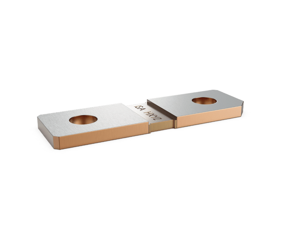
The BAL is the smallest busbar shunt in Isabellenhütte’s portfolio. It is ideal for 12 V battery management systems in all vehicles. In addition, it is potentially of interest to customers looking for a standard solution for the conceptual design of an energy storage system. Power losses of up to 12 W and a continuous current of 350 A with an R-value of 100 μOhm are no problem for the BAL. In the untinned version, the shunt offers the possibility for integration in a bus bar via laser welding, while the tinned version helps to reduce the contact resistance via a classic screw connection on a bus bar.
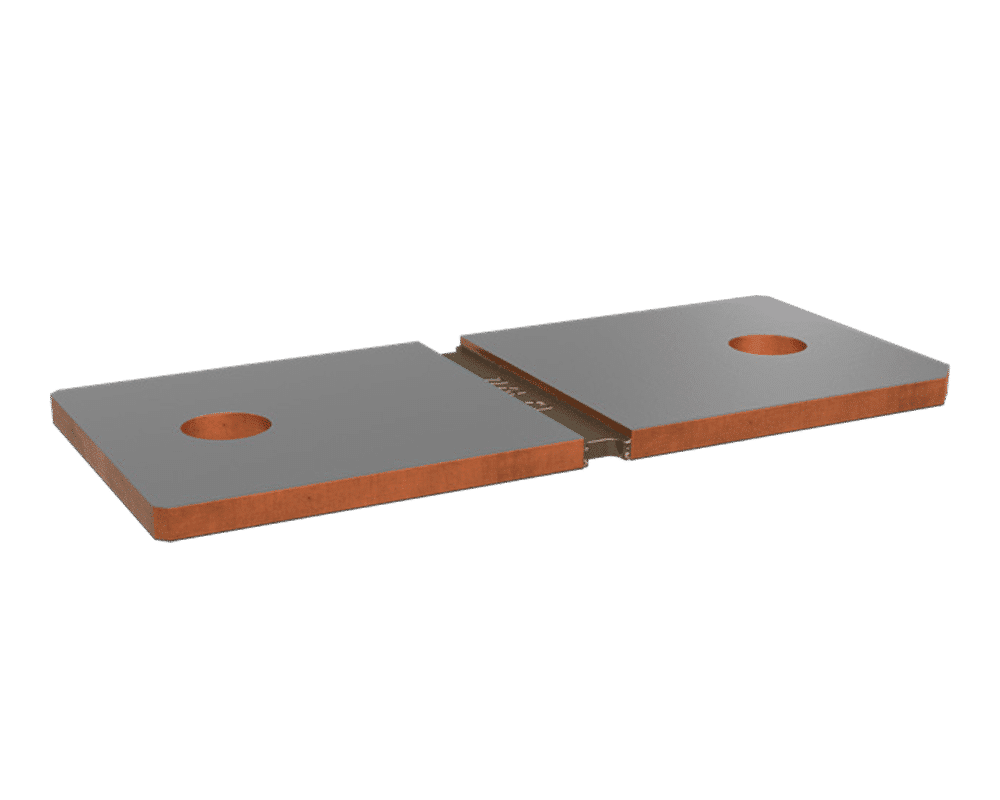
The standard busbar shunts also include the BAN. With a size of 84 x 36 x 3 mm (L x W x D) and a low resistance value of 25 μOhm, the BAN is ideal for monitoring very high currents above 1,000 A, especially for high voltage BMS applications in PHEVs and BEVs. The BAN is also available as a TCR-optimized version, making it ideal for highly integrated solutions with very high accuracy. In addition, the shunt is available with two or four mounting holes for screwing onto the bus bar.
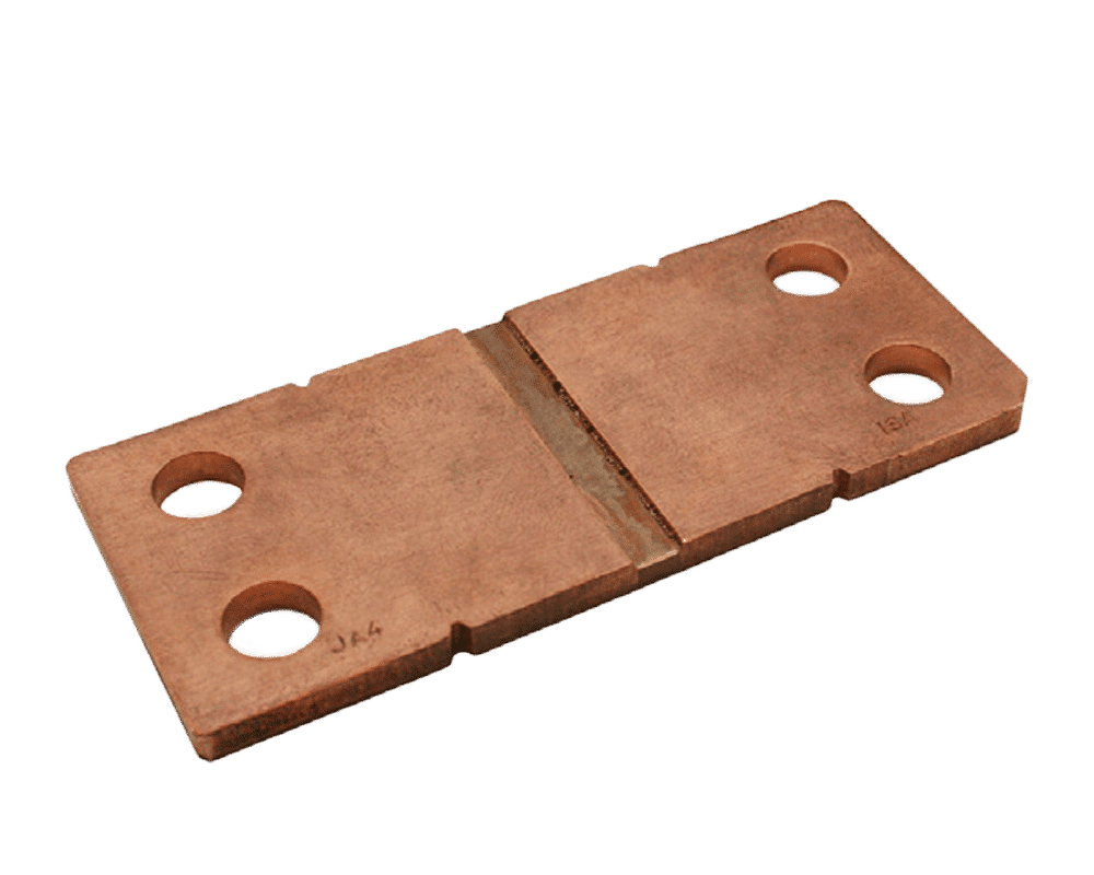
The BAX is currently the most powerful busbar shunt with the largest cross-section in the
standard portfolio (84 x 36 x 4 mm, L x W x D). It was developed specifically for high-voltage batteries in electric vehicles. It is designed for currents of over 1,000 A. Hybrid
vehicles use smaller electric motors with 48-volt systems, while pure electric vehicles are
high-voltage applications with voltages from 400 to 800 V or higher.
In this respect, the performance requirements for the component are also extremely
demanding. It must be able to handle a continuous high current, in some applications
500 to 1,000 A – permanently.
Such extreme power loads require resistors with a larger construction and lower resistance values to keep power losses to an absolute minimum. In addition, the BAX must also be able to withstand fault conditions such as short circuits when 2,000 or 5,000 A occur in a few milliseconds. In these high-current applications, the long-term stability of the busbar shunt is also crucial, as this has a direct influence on the residual range indicator in the vehicle. The more accurately the current can be measured over a long period of time, even at different temperatures, the more accurate the indication of the remaining range will be. The BAX meets the high requirements for fault tolerance over the life cycle of the component. The extremely low-ohmic BAX shunt is currently available in two variants; one with a resistance value of 20 μOhm, the other with a corresponding value of 5 μOhm.
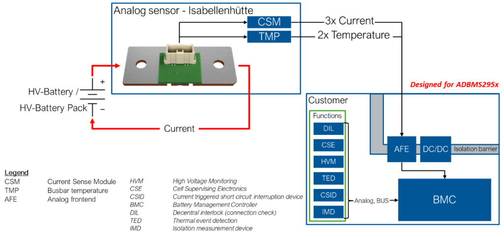
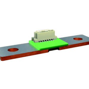
The analog sensor with PCB is a busbar shunt that can either be developed on a customer-specific basis or selected from Isabellenhütte’s standard product range. In addition, it contains a soldered-on printed circuit board (PCB), via which, among other things, direct tapping of the measurement signals is possible. Furthermore, depending on the configura¬tion, the temperature can be measured via NTCs (Negative Temperature Coefficient Thermistors) on the PCB and the resulting values can be used to compensate for the temperature coefficient.
Depending on the configuration, the analog sensor thus fulfills two of the main functions of a battery management system: current measurement (CSM) and temperature measure¬ment (TMP).
On the one hand, this ensures reliable transmission of measurement signals and also eliminates an additional process step. A connector is used to tap the voltage and tempera¬ture values and transmits the analog signal to the customer’s higher-level system.
The advantage for the user: The user gets a very good measurement signal because the PCB is placed exactly where the temperature coefficient is most favorable. If the user chooses his own contacting, this could be at a point where the TCR cannot be measured optimally, so that the measurement result is negatively influenced. On the other hand, with the PCB applied directly to the edge of the resistance material, the best possible pickup of the measurement signal is guaranteed.
The analog sensor with PCB also promises greater flexibility in terms of installation space: The system does not need to be designed in a special way so that the shunt and separate PCB are as close to each other as possible. It should be noted that the lead to the higher-level PCB can act like an antenna and thus interference can be received. However, this problem can be solved with a twisted or shielded lead.
Further variants – with different resistance values and shunt dimensions, and with ISO26262 qualification and more – are currently in the development phase and can be requested.
Another plus: On request, Isabellenhütte can laser the actual R-value of each manufactured component, including the temperature coefficient curve, onto the shunt in the form of a DMC code. The customer thus receives a “quasi-plug-and-play” solution and can use it immediately in the target system.
An alternative to connecting the shunt via a PCB with connector is to subsequently attach a PCB (developed by the customer) via a press-fit connection.
In this area, Isabellenhütte has responded to market requirements by providing another contacting option with press-fit connections, which allows the customer’s main PCB for the application to be directly contacted with the shunt via the press-fit pins. The attach¬ment of the press-fit pins offers some flexibility in terms of the position and number. In the areas of the press-fit pins, the busbar shunt must be uncoated, whereas coating is possible at the connection points to the bus bar in order to reduce the contact resistance.
The press-fit pins are conventional press-fit connections in accordance with IEC 60352-5. Isabellenhütte offers three different standard heights for these pins, although custom heights and other pin variations are also possible.
Three BAS shunts with R-values of 35, 50 and 100 μOhm and two press-fit pins each are available as standard. Customized designs can be easily implemented.
The advantages of this press-fit technology include the ability to quickly create connections without soldering. In addition, the distance of the PCB from the shunt provides protection in case of excessive temperatures at the shunt, which could possibly damage the PCB. Furthermore, at high currents, the distance between the PCB and the shunt can also reduce the influence of the magnetic fields on the semiconductors located on the PCB, which are sensitive in some areas.
Contacting a busbar shunt with a PCB or press-fit pins covers nearly 80 – 90% of the total busbar shunt market. In addition to these two solutions, another contacting option should be briefly mentioned: a flex lead applied to the shunt, the bonding of wires to the shunt, THT (through-hole technology) construction. The remaining solutions, such as flex lead or wire bonding, also play only a minor role for cost and technology reasons. The THT design is mostly used in industry, but less so in the automotive industry.
The key point of the BAx series, apart from its suitability for high-current applications – from electric vehicles to welding equipment – is the flexibility in terms of contacting to the customer’s measuring system. Depending on installation space, size and measurement requirements, users can choose from numerous options: according to resistance values, tinned/untinned design, with integrated printed circuit board, soldered pins or from individual solutions such as flex cables or metal injection moulding.
In the consultation, it is important for Isabellenhütte to show that the good properties of the busbar shunts can only be used optimally if the customer-side connection within the application is also considered. The contacting of the current sensor is part of the best possible measurement result. A wide variety of influencing variables must be taken into account in advance. Isabellenhütte will be happy to advise you on the development of a viable measurement solution that takes all influencing factors into account.
Isabellenhütte. “Busbar Shunts for Current Measurement in E-Mobility” Published August 2023. IHH_WP_busbar_shunts_for_current_measurement_emobility_en.pdf (isabellenhuette.de)